Part Number:

05.F0.010-0029

Manufacturer: KEB
Series: F0 Combivert Control Cabinet Series
  • Rated 4.4 (18 total ratings)
  • Straightforward Pricing: No Rush Fees, No Credit Card Fees
  • Call for Expedited Shipping and Product Condition Options
Free Ground Shipping
Worldwide Delivery
Repair Options Available

The KEB 05.F0.010-0029 is part of the F0 Combivert Control Cabinet Series and operates at an input voltage range of 0-Segnale = -30…5 VDC, 1-Segnale = 13…30 VDC. The device communicates via the KEB-DIN 66019 protocol and supports up to 35 V overvoltage protection. Its diagnosis capabilities are indicated by green LEDs.

Preparing your secure checkout page...

Warranty
1-year-warranty Wake Industrial Warranty
Shipping
DHL Logo FedEx Logo
UPS Logo Freight Logo
DHL Logo FedEx Logo UPS Logo Freight Logo
Payment
Visa Logo AmEx Logo
Mastercard Logo Wire transfer Logo
Visa Logo AmEx Logo Mastercard Logo Wire transfer Logo
To Speak to a sales representative for pricing and lead time:

Product Description

This KEB 05.F0.010-0029 Inverter-PCB is a highly versatile component designed to handle demanding industrial automation needs. KEB company has a strong reputation for developing innovative solutions for commercial and industrial uses.

This 05.F0.010-0029 Inverter-PCB works with a comprehensive range of input voltage options and protections and stands out for its high reliability. It has a 0-Segnale input voltage range from -30 to 5 VDC and a 1-Segnale range from 13 to 30 VDC by allowing it to function across various power conditions. This flexibility is further increased by an overvoltage tolerance of up to 35 V for brief 0.5-second intervals by ensuring stability even under challenging electrical conditions. The operating voltage is 24 VDC (typical) with a range between 15 and 30 VDC including ripple. In terms of connectivity and communication, this F0 Combivert Control Cabinet Series inverter PCB is built with the EB-DIN 66019 protocol which is compatible with ANSI X3.28 and ISO 1745 standards, making it suitable for integration in diverse setups. Diagnostic feedback is provided through LED indicators for TxD, RxD and operating voltage by allowing for easy on-the-spot checking of system health.

The 05.F0.010-0029 Inverter-PCB has connection options that include both plug and screw techniques for installation and the bus structure is designed as a closed line with terminating resistors by supporting stable communication. It uses shielded and twisted 4/2-wire cables with a wave impedance of 80 to 120 Ohm. It allows for a maximum cable length of up to 1000 meters and supports up to 32 units without a line driver for larger systems. It has a switchable terminal resistance of 50 Ohms which holds selectable NPN/PNP input characteristics and an RS485 interface supporting both half and full duplex modes.

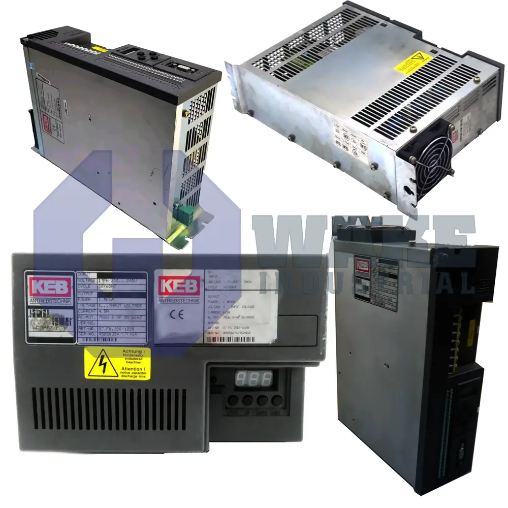
05.F0.010-0029 Technical Specifications

Input Voltage: 0-Segnale = -30…5 VDC 1-Segnale = 13…30 VDC
Maximum Units: max. 32 units without line driver
Terminal Resistance: 150 ý switchable
Input Characteristic: NPN/PNP selectable
Rs485 Interface: Full and Half Duplex
Internal Line Potential: Firmly wired internally
Type: Inverter PCB
Overvoltage Protection: up to 35 V (t = 0.5 s)
Operating Voltage: 24 VDC typical, 15…30 VDC inclusive ripple
Communication Protocol: KEB-DIN 66019 (ANSI X3.28, ISO 1745)
Diagnosis: TxD, RxD and operating voltage by LED (green)
Connection: Plug and screw technique
Bus Structure: Line, closed at both ends with the terminating resistor
Medium: 4/2-wire cables, shielded, twisted, wave impedance 80…120 Ohm
Cable Length: max. 1000 m

Frequently Asked Questions about 05.F0.010-0029


Q: How does the KEB 05.F0.010-0029 Inverter-PCB handle brief overvoltage?

A: It withstands overvoltage up to 35 V for a maximum of 0.5 seconds, offering protection during voltage spikes.

Q: Which communication protocol is used in the KEB 05.F0.010-0029 Inverter-PCB?

A: This inverter-PCB uses the EB-DIN 66019 protocol, compliant with ANSI X3.28 and ISO 1745 standards for flexible integration.

Q: What is the input voltage range for the KEB 05.F0.010-0029 Inverter-PCB?

A: The input voltage range is -30 to 5 VDC for 0-Segnale and 13 to 30 VDC for 1-Segnale accommodating various operating conditions.

Q: What type of bus structure does the KEB 05.F0.010-0029 Inverter-PCB use?

A: The PCB uses a closed line bus structure with terminating resistors at both ends for stable communication.

Q: How many units can the KEB 05.F0.010-0029 support on a single bus without a line driver?

A: The inverter-PCB can support up to 32 units on the bus without needing a line driver.

Internal Product Review

  • ‘‘The KEB 05.F0.010-0029 F0 Combivert Control Cabinet Series Inverter-PCB impresses with its durability and consistent performance under varied conditions. Its wide input voltage range, resilience to brief overvoltage and stable operation at 24 VDC make it a dependable choice for industrial automation tasks.’’

Motion Industries logo
3M logo
IBM logo
Gexpro Logo
Caterpillar logo
NASA logo
Ford logo
Vallen logo