Preparing your secure checkout page...
Warranty
Wake Industrial Warranty
To Speak to a sales representative for pricing and lead time:
Product Description
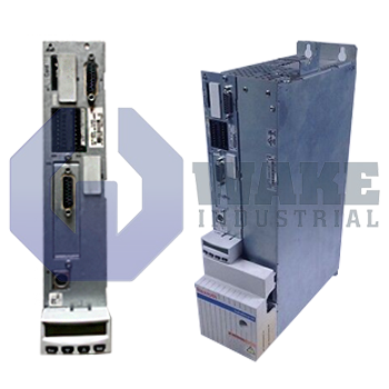
CSH01.3C-PL-ENN-CCD-NN-S-NN-FW is a control section. It is one of the four components that make up a IndraDrive motor controller. Different types of control sections are available to satisfy different customer requirements. The CSH01.3C-PL-ENN-CCD-NN-S-NN-FW is an advanced and configurable control section. The basic unit of the control section has slots for optional modules. Operators can order encoder modules and other optional modules to suit their particular requirements. Each control section has a master communication interface. The master communication module on the CSH01.3C-PL-ENN-CCD-NN-S-NN-FW is a parallel interface. This interface 16 digital inputs and 16 digital outputs. The
Inputs and outputs are grouped into sets of four inputs and four outputs. Other master communication options include multi-Ethernet, Profibus and SERCOS. The cross communication (CCD) module installed on the control section supports SERCOS III standard.
This CCD module serves as the master unit for communication between connected drive controllers. The two interfaces on the CCD module correspond to the IEEE 802.3 standard. The recommended cable types for use with the CCD module is Cat5e. The maximum supported cable length is 100 meters. The minimum bending radius for these cables is 48.75 millimeters with flexible installation and 32.5 millimeters with permanent installation. Bosch supplies long Cat5e cables measuring 30 meters and short cables measuring 0.55 meters. The CSH01.3C-PL-ENN-CCD-NN-S-NN-FW control section works with a standard control panel that has a single-display digital display and four-button keypad. This control panel does not support hot plug and must be connected when the power section is powered off. The control panel can be used for several operations, such as setting the drive address, setting transmission power for the SERCOS interface, establishing position data reference, viewing the error memory, setting analog outputs and starting basic load defaults procedure.